Future projections of Antarctic ice shelf melting

Climate change will increase ice shelf melt rates around Antarctica. That’s the not-very-surprising conclusion of my latest modelling study, done in collaboration with both Australian and German researchers, which was just published in Journal of Climate. Here’s the less intuitive result: much of the projected increase in melt rates is actually linked to a decrease in sea ice formation.

That’s a lot of different kinds of ice, so let’s back up a bit. Sea ice is just frozen seawater. But ice shelves (as well as ice sheets and icebergs) are originally formed of snow. Snow falls on the Antarctic continent, and over many years compacts into a system of interconnected glaciers that we call an ice sheet. These glaciers flow downhill towards the coast. If they hit the coast and keep going, floating on the ocean surface, the floating bits are called ice shelves. Sometimes the edges of ice shelves will break off and form icebergs, but they don’t really come into this story.

Climate models don’t typically include ice sheets, or ice shelves, or icebergs. This is one reason why projections of sea level rise are so uncertain. But some standalone ocean models do include ice shelves. At least, they include the little pockets of ocean beneath the ice shelves – we call them ice shelf cavities – and can simulate the melting and refreezing that happens on the ice shelf base.

We took one of these ocean/ice-shelf models and forced it with the atmospheric output of regular climate models, which periodically make projections of climate change from now until the end of the century. We completed four different simulations, consisting of two different greenhouse gas emissions scenarios (“Representative Concentration Pathways” or RCPs) and two different choices of climate model (“ACCESS 1.0”, or “MMM” for the multi-model mean). Each simulation required 896 processors on the supercomputer in Canberra. By comparison, your laptop or desktop computer probably has about 4 processors. These are pretty sizable models!

In every simulation, and in every region of Antarctica, ice shelf melting increased over the 21st century. The total increase ranged from 41% to 129% depending on the scenario. The largest increases occurred in the Amundsen Sea region, marked with red circles in the maps below, which happens to be the region exhibiting the most severe melting in recent observations. In the most extreme scenario, ice shelf melting in this region nearly quadrupled.

Percent change in ice shelf melting, caused by the ocean, during the four future projections. The values are shown for all of Antarctica (written on the centre of the continent) as well as split up into eight sectors (colour-coded, written inside the circles). Figure 3 of Naughten et al., 2018, © American Meteorological Society.

So what processes were causing this melting? This is where the sea ice comes in. When sea ice forms, it spits out most of the salt from the seawater (brine rejection), leaving the remaining water saltier than before. Salty water is denser than fresh water, so it sinks. This drives a lot of vertical mixing, and the heat from warmer, deeper water is lost to the atmosphere. The ocean surrounding Antarctica is unusual in that the deep water is generally warmer than the surface water. We call this warm, deep water Circumpolar Deep Water, and it’s currently the biggest threat to the Antarctic Ice Sheet. (I say “warm” – it’s only about 1°C, so you wouldn’t want to go swimming in it, but it’s plenty warm enough to melt ice.)

In our simulations, warming winters caused a decrease in sea ice formation. So there was less brine rejection, causing fresher surface waters, causing less vertical mixing, and the warmth of Circumpolar Deep Water was no longer lost to the atmosphere. As a result, ocean temperatures near the bottom of the Amundsen Sea increased. This better-preserved Circumpolar Deep Water found its way into ice shelf cavities, causing large increases in melting.

Slices through the Amundsen Sea – you’re looking at the ocean sideways, like a slice of birthday cake, so you can see the vertical structure. Temperature is shown on the top row (blue is cold, red is warm); salinity is shown on the bottom row (blue is fresh, red is salty). Conditions at the beginning of the simulation are shown in the left 2 panels, and conditions at the end of the simulation are shown in the right 2 panels. At the beginning of the simulation, notice how the warm, salty Circumpolar Deep Water rises onto the continental shelf from the north (right side of each panel), but it gets cooler and fresher as it travels south (towards the left) due to vertical mixing. At the end of the simulation, the surface water has freshened and the vertical mixing has weakened, so the warmth of the Circumpolar Deep Water is preserved. Figure 8 of Naughten et al., 2018, © American Meteorological Society.

This link between weakened sea ice formation and increased ice shelf melting has troubling implications for sea level rise. The next step is to simulate the sea level rise itself, which requires some model development. Ocean models like the one we used for this study have to assume that ice shelf geometry stays constant, so no matter how much ice shelf melting the model simulates, the ice shelves aren’t allowed to thin or collapse. Basically, this design assumes that any ocean-driven melting is exactly compensated by the flow of the upstream glacier such that ice shelf geometry remains constant.

Of course this is not a good assumption, because we’re observing ice shelves thinning all over the place, and a few have even collapsed. But removing this assumption would necessitate coupling with an ice sheet model, which presents major engineering challenges. We’re working on it – at least ten different research groups around the world – and over the next few years, fully coupled ice-sheet/ocean models should be ready to use for the most reliable sea level rise projections yet.

A modified version of this post appeared on the EGU Cryospheric Sciences Blog.

We just published in Nature Geoscience

It turns out that when you submit a paper to a journal like Nature Geoscience “just in case, we have nothing to lose, they’ll probably reject it straight away”…sometimes you are unexpectedly successful.

Read it here!

Assorted media coverage:

More detailed post to come…

My Research with Steve

Almost four years ago I took a job as a summer student of Dr. Steve Easterbrook, in the software engineering lab of the University of Toronto. This was my first time taking part in research, but also my first time living away from home and my first time using a Unix terminal (both of which are challenging, but immensely rewarding, life skills).

While working with Steve I discovered that climate model output is really pretty (an opinion which hasn’t changed in the four years since) and that climate models are really hard to install (that hasn’t changed either).

At Steve’s suggestion I got a hold of the code for various climate models and started to pick it apart. By the end of the summer I had created a series of standardised diagrams showing the software architecture of each model.

These diagrams proved to be really useful communication tools: we presented our work at AGU the following December, and at NCAR about a year after that, to very positive feedback. Many climate modellers we met at these conferences were pleased to have a software diagram of the model they used (which is very useful to show during presentations), but they were generally more interested in the diagrams for other models, to see how other research groups used different software structures to solve the same problems. “I had no idea they did it like that,” was a remark I heard more than a few times.

Between my undergrad and PhD, I went back to Toronto for a month where I analysed the model code more rigorously. We made a new set of diagrams which was more accurate: the code was sorted into components based on dependency structure, and the area of each component in a given diagram was exactly proportional to the line count of its source code.

Here is the diagram we made for the GFDL-ESM2M model, which is developed at the Geophysical Fluid Dynamics Laboratory in Princeton:

We wrote this all up into a paper, submitted it to GMD, and after several months and several rounds of revision it was published just yesterday! The paper is open access, and can be downloaded for free here. It’s my first paper as lead author which is pretty exciting.

I could go on about all the interesting things we discovered while comparing the diagrams, but that’s all in the paper. Instead I wanted to talk about what’s not in the paper: the story of the long and winding journey we took to get there, from my first day as a nervous summer student in Toronto to the final publication yesterday. These are the stories you don’t read about in scientific papers, which out of necessity detail the methodology as if the authors knew exactly where they were going and got there using the shortest possible path. Science doesn’t often work like that. Science is about messing around and exploring and getting a bit lost and eventually figuring it out and feeling like a superhero when you do. And then writing it up as if it was easy.

I also wanted to express my gratitude to Steve, who has been an amazing source of support, advice, conversations, book recommendations, introductions to scientists, and career advice. I’m so happy that I got to be your student. See you before long on one continent or another!

A Simple Stochastic Climate Model: Climate Sensitivity

I haven’t forgotten about this project! Read the introduction and ODE derivation if you haven’t already.

Last time I derived the following ODE for temperature T at time t:

where S and τ are constants, and F(t) is the net radiative forcing at time t. Eventually I will discuss each of these terms in detail; this post will focus on S.

At equilibrium, when dT/dt = 0, the ODE necessitates T(t) = S F(t). A physical interpretation for S becomes apparent: it measures the equilibrium change in temperature per unit forcing, also known as climate sensitivity.

A great deal of research has been conducted with the aim of quantifying climate sensitivity, through paleoclimate analyses, modelling experiments, and instrumental data. Overall, these assessments show that climate sensitivity is on the order of 3 K per doubling of CO2 (divide by 5.35 ln 2 W/m2 to convert to warming per unit forcing).

The IPCC AR4 report (note that AR5 was not yet published at the time of my calculations) compared many different probability distribution functions (PDFs) of climate sensitivity, shown below. They follow the same general shape of a shifted distribution with a long tail to the right, and average 5-95% confidence intervals of around 1.5 to 7 K per doubling of CO2.

Box 10.2, Figure 1 of the IPCC AR4 WG1: Probability distribution functions of climate sensitivity (a), 5-95% confidence intervals (b).

These PDFs generally consist of discrete data points that are not publicly available. Consequently, sampling from any existing PDF would be difficult. Instead, I chose to create my own PDF of climate sensitivity, modelled as a log-normal distribution (e raised to the power of a normal distribution) with the same shape and bounds as the existing datasets.

The challenge was to find values for μ and σ, the mean and standard deviation of the corresponding normal distribution, such that for any z sampled from the log-normal distribution,

Since erf, the error function, cannot be evaluated analytically, this two-parameter problem must be solved numerically. I built a simple particle swarm optimizer to find the solution, which consistently yielded results of μ = 1.1757, σ = 0.4683.

The upper tail of a log-normal distribution is unbounded, so I truncated the distribution at 10 K, consistent with existing PDFs (see figure above). At the beginning of each simulation, climate sensitivity in my model is sampled from this distribution and held fixed for the entire run. A histogram of 106 sampled points, shown below, has the desired characteristics.

Histogram of 106 points sampled from the log-normal distribution used for climate sensitivity in the model.

Histogram of 106 points sampled from the log-normal distribution used for climate sensitivity in the model.

Note that in order to be used in the ODE, the sampled points must then be converted to units of Km2/W (warming per unit forcing) by dividing by 5.35 ln 2 W/m2, the forcing from doubled CO2.

A Simple Stochastic Climate Model: Deriving the Backbone

Last time I introduced the concept of a simple climate model which uses stochastic techniques to simulate uncertainty in our knowledge of the climate system. Here I will derive the backbone of this model, an ODE describing the response of global temperature to net radiative forcing. This derivation is based on unpublished work by Nathan Urban – many thanks!

In reality, the climate system should be modelled not as a single ODE, but as a coupled system of hundreds of PDEs in four dimensions. Such a task is about as arduous as numerical science can get, but dozens of research groups around the world have built GCMs (General Circulation Models, or Global Climate Models, depending on who you talk to) which come quite close to this ideal.

Each GCM has taken hundreds of person-years to develop, and I only had eight weeks. So for the purposes of this project, I treat the Earth as a spatially uniform body with a single temperature. This is clearly a huge simplification but I decided it was necessary.

Let’s start by defining T1(t) to be the absolute temperature of this spatially uniform Earth at time t, and let its heat capacity be C. Therefore,

C \: T_1(t) = E

where E is the change in energy required to warm the Earth from 0 K to temperature T1. Taking the time derivative of both sides,

C \: \frac{dT_1}{dt} = \frac{dE}{dt}

Now, divide through by A, the surface area of the Earth:

c \: \frac{dT_1}{dt} = \frac{1}{A} \frac{dE}{dt}

where c = C/A is the heat capacity per unit area. Note that the right side of the equation, a change in energy per unit time per unit area, has units of W/m2. We can express this as the difference of incoming and outgoing radiative fluxes, I(t) and O(t) respectively:

c \: \frac{dT_1}{dt} = I(t)- O(t)

By the Stefan-Boltzmann Law,

c \: \frac{dT_1}{dt} = I(t) - \epsilon \sigma T_1(t)^4

where ϵ is the emissivity of the Earth and σ is the Stefan-Boltzmann constant.

To consider the effect of a change in temperature, suppose that T1(t) = T0 + T(t), where T0 is an initial equilibrium temperature and T(t) is a temperature anomaly. Substituting into the equation,

c \: \frac{d(T_0 + T(t)
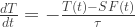
)}{dt} = I(t) - \epsilon \sigma (T_0 + T(t))^4

Noting that T0 is a constant, and also factoring the right side,

c \: \frac{dT}{dt} = I(t) - \epsilon \sigma T_0^4 (1 + \tfrac{T(t)}{T_0})^4

Since the absolute temperature of the Earth is around 280 K, and we are interested in perturbations of around 5 K, we can assume that T(t)/T0 ≪ 1. So we can linearize (1 + T(t)/T0)4 using a Taylor expansion about T(t) = 0:

c \: \frac{dT}{dt} = I(t) - \epsilon \sigma T_0^4 (1 + 4 \tfrac{T(t)}{T_0} + O[(\tfrac{T(t)}{T_0})^2])

\approx I(t) - \epsilon \sigma T_0^4 (1 + 4 \tfrac{T(t)}{T_0})

= I(t) - \epsilon \sigma T_0^4 - 4 \epsilon \sigma T_0^3 T(t)

Next, let O0 = ϵσT04 be the initial outgoing flux. So,

c \: \frac{dT}{dt} = I(t) - O_0 - 4 \epsilon \sigma T_0^3 T(t)

Let F(t) = I(t) – O0 be the radiative forcing at time t. Making this substitution as well as dividing by c, we have

\frac{dT}{dt} = \frac{F(t) - 4 \epsilon \sigma T_0^3 T(t)}{c}

Dividing each term by 4ϵσT03 and rearranging the numerator,

\frac{dT}{dt} = - \frac{T(t) - \tfrac{1}{4 \epsilon \sigma T_0^3} F(t)}{\tfrac{c}{4 \epsilon \sigma T_0^3}}

Finally, let S = 1/(4ϵσT03) and τ = cS. Our final equation is

\frac{dT}{dt} = - \frac{T(t) - S F(t)}{\tau}

While S depends on the initial temperature T0, all of the model runs for this project begin in the preindustrial period when global temperature is approximately constant. Therefore, we can treat S as a parameter independent of initial conditions. As I will show in the next post, the uncertainty in S based on climate system dynamics far overwhelms any error we might introduce by disregarding T0.

A Simple Stochastic Climate Model: Introduction

This winter I took a course in computational physics, which has probably been my favourite undergraduate course to date. Essentially it was an advanced numerical methods course, but from a very practical point of view. We got a lot of practice using numerical techniques to solve realistic problems, rather than just analysing error estimates and proving conditions of convergence. As a math student I found this refreshing, and incredibly useful for my research career.

We all had to complete a term project of our choice, and I decided to build a small climate model. I was particularly interested in the stochastic techniques taught in the course, and given that modern GCMs and EMICs are almost entirely deterministic, it was possible that I could contribute something original to the field.

The basic premise of my model is this: All anthropogenic forcings are deterministic, and chosen by the user. Everything else is determined stochastically: parameters such as climate sensitivity are sampled from probability distributions, whereas natural forcings are randomly generated but follow the same general pattern that exists in observations. The idea is to run this model with the same anthropogenic input hundreds of times and build up a probability distribution of future temperature trajectories. The spread in possible scenarios is entirely due to uncertainty in the natural processes involved.

This approach mimics the real world, because the only part of the climate system we have full control over is our own actions. Other influences on climate are out of our control, sometimes poorly understood, and often unpredictable. It is just begging to be modelled as a stochastic system. (Not that it is actually stochastic, of course; in fact, I understand that nothing is truly stochastic, even random number generators – unless you can find a counterexample using quantum mechanics? But that’s a discussion for another time.)

A word of caution: I built this model in about eight weeks. As such, it is highly simplified and leaves out a lot of processes. You should never ever use it for real climate projections. This project is purely an exercise in numerical methods, and an exploration of the possible role of stochastic techniques in climate modelling.

Over the coming weeks, I will write a series of posts that explains each component of my simple stochastic climate model in detail. I will show the results from some sample simulations, and discuss how one might apply these stochastic techniques to existing GCMs. I also plan to make the code available to anyone who’s interested – it’s written in Matlab, although I might translate it to a free language like Python, partly because I need an excuse to finally learn Python.

I am very excited to finally share this project with you all! Check back soon for the next installment.

Milestones

You may have already heard that carbon dioxide concentrations have surpassed 400 ppm. The most famous monitoring station, Mauna Loa Observatory in Hawaii, reached this value on May 9th. Due to the seasonal cycle, CO2 levels began to decline almost immediately thereafter, but next year they will easily blow past 400 ppm.

Of course, this milestone is largely arbitrary. There’s nothing inherently special about 400 ppm. But it’s a good reminder that while we were arguing about taxation, CO2 levels continued to quietly tick up and up.


In happier news, John Cook and others have just published the most exhaustive survey of the peer-reviewed climate literature to date. Read the paper here (open access), and a detailed but accessible summary here. Unsurprisingly, they found the same 97% consensus that has come up over and over again.

Cook et al read the abstracts of nearly 12 000 papers published between 1991 and 2011 – every single hit from the ISI Web of Science with the keywords “global climate change” or “global warming”. Several different people categorized each abstract, and the authors were contacted whenever possible to categorize their own papers. Using several different methods like this makes the results more reliable.

Around two-thirds of the studies, particularly the more recent ones, didn’t mention the cause of climate change. This is unsurprising, since human-caused warming has been common knowledge in the field for years. Similarly, seismology papers don’t usually mention that plate tectonics cause earthquakes, particularly in the abstracts where space is limited.

Among the papers which did express a position, 97.1% said climate change was human-caused. Again, unsurprising to anyone working in the field, but it’s news to many members of the public. The study has been widely covered in the mainstream media – everywhere from The Guardian to The Australian – and even President Obama’s Twitter feed.


Congratulations are also due to Andrew Weaver, my supervisor from last summer, who has just been elected to the British Columbia provincial legislature. He is not only the first-ever Green Party MLA in BC’s history, but also (as far as I know) the first-ever climate scientist to hold public office.

Governments the world over are sorely in need of officials who actually understand the problem of climate change. Nobody fits this description better than Andrew, and I think he is going to be great. The large margin by which he won also indicates that public support for climate action is perhaps higher than we thought.


Finally, my second publication came out this week in Climate of the Past. It describes an EMIC intercomparison project the UVic lab conducted for the next IPCC report, which I helped out with while I was there. The project was so large that we split the results into two papers (the second of which is in press in Journal of Climate). This paper covers the historical experiments – comparing model results from 850-2005 to observations and proxy reconstructions – as well as some idealized experiments designed to measure metrics such as climate sensitivity, transient climate response, and carbon cycle feedbacks.

A Visit to NCAR

Last week I was lucky enough to attend the Second Workshop on Coupling Technologies for Earth System Models, held at the National Center for Atmospheric Research (NCAR) in Boulder, Colorado, USA. I was excited just to visit NCAR, which is one of the top climate research facilities in the world. Not only is it packed full of interesting scientists and great museum displays, but it’s nestled in the Rocky Mountains and so the view from the conference room looks like this:

2013-02-21 13.46.43

Many of the visitors would spend large portions of the coffee breaks just staring out the window…

The conference was focused on couplers – the part of a climate model that ties all the other components (atmosphere, ocean, land, etc.) together. However, the presentations covered (as Rob Jacob put it) “everything that physical scientists don’t care about unless it stops working”. Since I consider myself a physical scientist, this included a lot of concepts I hadn’t thought about before:

  • Parallel processing: Since climate models are so big, it makes sense to multitask by splitting the work over many computer processors. You have to allocate the right number of processors to each component, though: if the atmosphere has too many processors, it will finish its timestep too quickly and sit there waiting until the ocean is done, and vice versa. This is called load balancing, and it gets very tricky as soon as the number of components exceeds two.
  • Scalability: The more processors you use, the faster the model runs, but the speed has diminishing returns. If you double the number of processors, you won’t quite double the speed, particularly if the number of processors exceeds 104 (a setup which is becoming increasingly affordable for large research groups). Historically, the coupler has not been a code bottleneck (limiting factor for model speed), but as the number of processors gets very large, that scenario is changing. We have to figure out the most efficient way to couple many small components together, so that climate model speed can continue to keep up with advances in computer hardware.
  • Standardization: Modelling groups across the world are communicating with each other more and more, and using each other’s code. Currently this requires a lot of modifications, because every climate model has a different structure. Everyone seems to agree that it would be great to have a standard interface that allowed you to plug any combination of components together, but of course everyone has a different idea of what that standard should be.
  • Fortran is still the best language for climate models, believe it or not, because it is the fastest language for the kinds of operations required. If a modern, accessible language like Python could compete based on speed, you can bet that new climate models like MPAS would use it.

I was at the conference with Steve Easterbrook and his new M.Sc. student Daniel Levy, presenting our bubble diagrams of model architecture. (If you haven’t already, read my AGU poster schpiel first, or none of this will make sense!) As interesting and useful as these diagrams are, there were some flaws in our original analysis:

  1. We didn’t use preprocessed code, meaning that each “model” is actually the code base for many different model configurations. So our estimate of model complexity based on line count is biased towards models which are very configurable, but might not actually be very complex. We can fix this by choosing specific configurations of each model (for consistency, the configuration used in CMIP5 or the equivalent EMIC AR5 intercomparison project) and obtaining preprocessed code from the corresponding institutions.
  2. We sorted the code into components (eg atmosphere) and sub-components (eg atmospheric aerosols) based on folder structure, which might not reflect the hierarchy of routines formed at runtime. Some modelling groups keep their files very organized, but often code from different parts of the model was mixed together, and separating it out was very much a judgement call. To fix this, we can sort based on the dependency structure (a massive tree graph showing which routines call which): all the descendants of the atmosphere driver are part of the atmosphere component, and so on.
  3. We made our diagrams in Microsoft PowerPoint, which is quite limited, and didn’t allow us to size the bubbles so their area was perfectly proportional to line count. Instead, we just had to eyeball it. We can fix this by using Adobe Illustrator, which is much more advanced and has this capability.

So far, we’ve repeated the analysis for the UK Met Office Model, version HadGEM2-ES. I created the dependency structure by going manually through every file and making good use of grep, which took hours and hours (although it was a nice, menial way to avoid studying for my courses!). Daniel is going to write a Fortran parser to make the job easier next time around. In the meantime, our HadGEM2-ES diagram is absolutely gorgeous and wonderfully accurate:
HadGEM2-ES
I will post future diagrams as they become available. We think the main use of these diagrams will be as communication tools between scientists, so they are free to use with attribution.

Just a few more weeks of classes, then I can enjoy some full-time research. Now that I’ve had a taste of being a proper scientist, it’s hard to go back!

The PETM

Lately I have been reading a lot about the Paleocene-Eocene Thermal Maximum, or PETM, which is my favourite paleoclimatic event (is it weird to have a favourite?) This episode of rapid global warming 55 million years ago is particularly relevant to our situation today, because it was clearly caused by greenhouse gases. Unfortunately, the rest of the story is far less clear.

Paleocene mammals

The PETM happened about 10 million years after the extinction that killed the dinosaurs. The Age of Mammals was well underway, although humans wouldn’t appear in any form for another few million years. It was several degrees warmer, to start with, than today’s conditions. Sea levels would have been higher, and there were probably no polar ice caps.

Then, over several thousand years, the world warmed by between 5 and 8°C. It seems to have happened in a few bursts, against a background of slower temperature increase. Even the deep ocean, usually a very stable thermal environment, warmed by at least 5°C. It took around a hundred thousand years for the climate system to recover.

Such rapid global warming hasn’t been seen since, although it’s possible (probable?) that human-caused warming will surpass this rate, if it hasn’t already. It is particularly troubling to realize that our species has never before experienced an event like the one we’re causing today. The climate has changed before, but humans generally weren’t there to see it.

The PETM is marked in the geological record by a sudden jump in the amount of “light” carbon in the climate system. Carbon comes in different isotopes, two of which are most important for climate analysis: carbon with 7 neutrons (13C), and carbon with 6 neutrons (12C). Different carbon cycle processes sequester these forms of carbon in different amounts. Biological processes like photosynthesis preferentially take 12C out of the air in the form of CO2, while geological processes like subduction of the Earth’s crust take anything that’s part of the rock. When the carbon comes back up, the ratios of 12C to 13C are preserved: emissions from the burning of fossil fuels, for example, are relatively “light” because they originated from the tissues of living organisms; emissions from volcanoes are more or less “normal” because they came from molten crust that was once the ocean floor.

In order to explain the isotopic signature of the PETM, you need to add to the climate system either a massive amount of carbon that’s somewhat enriched in light carbon, or a smaller amount of carbon that’s extremely enriched in light carbon, or (most likely) something in the middle. The carbon came in the form of CO2, or possibly CH4 that soon oxidized to form CO2. That, in turn, almost certainly caused the warming.

There was a lot of warming, though, so there must have been a great deal of carbon. We don’t know exactly how much, because the warming power of CO2 depends on how much is already present in the atmosphere, and estimates for initial CO2 concentration during the PETM vary wildly. However, the carbon injection was probably something like 5 trillion tonnes. This is comparable to the amount of carbon we could emit today from burning all our fossil fuel reserves. That’s a heck of a lot of carbon, and what nobody can figure out is where did it all come from?

Arguably the most popular hypothesis is methane hydrates. On continental shelves, methane gas (CH4) is frozen into the ocean floor. Microscopic cages of water contain a single molecule of methane each, but when the water melts the methane is released and bubbles up to the surface. Today there are about 10 trillion tonnes of carbon stored in methane hydrates. In the PETM the levels were lower, but nobody is sure by how much.

The characteristics of methane hydrates seem appealing as an explanation for the PETM. They are very enriched in 12C, meaning less of them would be needed to cause the isotopic shift. They discharge rapidly and build back up slowly, mirroring the sudden onset and slow recovery of the PETM. The main problem with the methane hydrate hypothesis is that there might not have been enough of them to account for the warming observed in the fossil record.

However, remember that in order to release their carbon, methane hydrates must first warm up enough to melt. So some other agent could have started the warming, which then triggered the methane release and the sudden bursts of warming. There is no geological evidence for any particular source – everything is speculative, except for the fact that something spat out all this CO2.

Magnified foraminifera

Don’t forget that where there is greenhouse warming, there is ocean acidification. The ocean is great at soaking up greenhouse gases, but this comes at a cost to organisms that build shells out of calcium carbonate (CaCO3, the same chemical that makes up chalk). CO2 in the water forms carbonic acid, which starts to dissolve their shells. Likely for this reason, the PETM caused a mass extinction of benthic foraminifera (foraminifera = microscopic animals with CaCO3 shells; benthic = lives on the ocean floor).

Other groups of animals seemed to do okay, though. There was a lot of rearranging of habitats – species would disappear in one area but flourish somewhere else – but no mass extinction like the one that killed the dinosaurs. The fossil record can be deceptive in this manner, though, because it only preserves a small number of species. By sheer probability, the most abundant and widespread organisms are most likely to appear in the fossil record. There could be many organisms that were less common, or lived in restricted areas, that went extinct without leaving any signs that they ever existed.

Climate modellers really like the PETM, because it’s a historical example of exactly the kind of situation we’re trying to understand using computers. If you add a few trillion tonnes of carbon to the atmosphere in a relatively short period of time, how much does the world warm and what happens to its inhabitants? The PETM ran this experiment for us in the real world, and can give us some idea of what to expect in the centuries to come. If only it had left more data behind for us to discover.

References:
Pagani et al., 2006
Dickens, 2011
McInerney and Wing, 2011

Climate Change and Atlantic Circulation

Today my very first scientific publication is appearing in Geophysical Research Letters. During my summer at UVic, I helped out with a model intercomparison project regarding the effect of climate change on Atlantic circulation, and was listed as a coauthor on the resulting paper. I suppose I am a proper scientist now, rather than just a scientist larva.

The Atlantic meridional overturning circulation (AMOC for short) is an integral part of the global ocean conveyor belt. In the North Atlantic, a massive amount of water near the surface, cooling down on its way to the poles, becomes dense enough to sink. From there it goes on a thousand-year journey around the world – inching its way along the bottom of the ocean, looping around Antarctica – before finally warming up enough to rise back to the surface. A whole multitude of currents depend on the AMOC, most famously the Gulf Stream, which keeps Europe pleasantly warm.

Some have hypothesized that climate change might shut down the AMOC: the extra heat and freshwater (from melting ice) coming into the North Atlantic could conceivably lower the density of surface water enough to stop it sinking. This happened as the world was coming out of the last ice age, in an event known as the Younger Dryas: a huge ice sheet over North America suddenly gave way, drained into the North Atlantic, and shut down the AMOC. Europe, cut off from the Gulf Stream and at the mercy of the ice-albedo feedback, experienced another thousand years of glacial conditions.

A shutdown today would not lead to another ice age, but it could cause some serious regional cooling over Europe, among other impacts that we don’t fully understand. Today, though, there’s a lot less ice to start with. Could the AMOC still shut down? If not, how much will it weaken due to climate change? So far, scientists have answered these two questions with “probably not” and “something like 25%” respectively. In this study, we analysed 30 climate models (25 complex CMIP5 models, and 5 smaller, less complex EMICs) and came up with basically the same answer. It’s important to note that none of the models include dynamic ice sheets (computational glacial dynamics is a headache and a half), which might affect our results.

Models ran the four standard RCP experiments from 2006-2100. Not every model completed every RCP, and some extended their simulations to 2300 or 3000. In total, there were over 30 000 model years of data. We measured the “strength” of the AMOC using the standard unit Sv (Sverdrups), where each Sv is 1 million cubic metres of water per second.

Only two models simulated an AMOC collapse, and only at the tail end of the most extreme scenario (RCP8.5, which quite frankly gives me a stomachache). Bern3D, an EMIC from Switzerland, showed a MOC strength of essentially zero by the year 3000; CNRM-CM5, a GCM from France, stabilized near zero by 2300. In general, the models showed only a moderate weakening of the AMOC by 2100, with best estimates ranging from a 22% drop for RCP2.6 to a 40% drop for RCP8.5 (with respect to preindustrial conditions).

Are these somewhat-reassuring results trustworthy? Or is the Atlantic circulation in today’s climate models intrinsically too stable? Our model intercomparison also addressed that question, using a neat little scalar metric known as Fov: the net amount of freshwater travelling from the AMOC to the South Atlantic.

The current thinking in physical oceanography is that the AMOC is more or less binary – it’s either “on” or “off”. When AMOC strength is below a certain level (let’s call it A), its only stable state is “off”, and the strength will converge to zero as the currents shut down. When AMOC strength is above some other level (let’s call it B), its only stable state is “on”, and if you were to artificially shut it off, it would bounce right back up to its original level. However, when AMOC strength is between A and B, both conditions can be stable, so whether it’s on or off depends on where it started. This phenomenon is known as hysteresis, and is found in many systems in nature.

This figure was not part of the paper. I made it just now in MS Paint.

Here’s the key part: when AMOC strength is less than A or greater than B, Fov is positive and the system is monostable. When AMOC strength is between A and B, Fov is negative and the system is bistable. The physical justification for Fov is its association with the salt advection feedback, the sign of which is opposite Fov: positive Fov means the salt advection feedback is negative (i.e. stabilizing the current state, so monostable); a negative Fov means the salt advection feedback is positive (i.e. reinforcing changes in either direction, so bistable).

Most observational estimates (largely ocean reanalyses) have Fov as slightly negative. If models’ AMOCs really were too stable, their Fov‘s should be positive. In our intercomparison, we found both positives and negatives – the models were kind of all over the place with respect to Fov. So maybe some models are overly stable, but certainly not all of them, or even the majority.

As part of this project, I got to write a new section of code for the UVic model, which calculated Fov each timestep and included the annual mean in the model output. Software development on a large, established project with many contributors can be tricky, and the process involved a great deal of head-scratching, but it was a lot of fun. Programming is so satisfying.

Beyond that, my main contribution to the project was creating the figures and calculating the multi-model statistics, which got a bit unwieldy as the model count approached 30, but we made it work. I am now extremely well-versed in IDL graphics keywords, which I’m sure will come in handy again. Unfortunately I don’t think I can reproduce any figures here, as the paper’s not open-access.

I was pretty paranoid while coding and doing calculations, though – I kept worrying that I would make a mistake, never catch it, and have it dredged out by contrarians a decade later (“Kate-gate”, they would call it). As a climate scientist, I suppose that comes with the job these days. But I can live with it, because this stuff is just so darned interesting.